ADTRAN MX410 Spezifikationen
Stöbern Sie online oder laden Sie Spezifikationen nach Vernetzung ADTRAN MX410 herunter. ADTRAN MX410 Specifications Benutzerhandbuch
- Seite / 134
- Inhaltsverzeichnis
- LESEZEICHEN
- MX410/MX412 1
- System Manual 1
- Trademarks 2
- To the Holder of the Manual 2
- Revision History 3
- Conventions 3
- HAZARD CLASSIFICATIONS 4
- Training 5
- Contents 7
- MX410/MX412 System Manual 10
- 61189500L1-1F xi 11
- 61189500L1-1F xiii 13
- Section 1 15
- Introduction 15
- Figure 1-3. MX410 Overview 16
- Figure 1-4. MX412 Overview 16
- FEATURES 17
- 1-4 61189500L1-1F 18
- Section 2 19
- Engineering Guidelines 19
- POWER REQUIREMENTS 20
- POWER DISSIPATION 21
- 2-4 61189500L1-1F 22
- Section 3 23
- Application Guidelines 23
- MX410 DATA PATH BLOCK DIAGRAM 24
- Drop and Continue Application 25
- 3-4 61189500L1-1F 26
- MX410 Data Path Block Diagram 27
- 61189500L1-1F 3-5 27
- 3-6 61189500L1-1F 28
- Drop and Insert Application 29
- 3-8 61189500L1-1F 30
- 61189500L1-1F 3-9 31
- 3-10 61189500L1-1F 32
- 61189500L1-1F 3-11 33
- Central 34
- Remote Site #1 34
- (Required Equipment Per Site) 35
- 3-14 61189500L1-1F 36
- 61189500L1-1F 3-15 37
- 3-16 61189500L1-1F 38
- 61189500L1-1F 3-17 39
- 3-18 61189500L1-1F 40
- 61189500L1-1F 3-19 41
- 3-20 61189500L1-1F 42
- Section 4 43
- Installation 43
- RACKMOUNT 44
- WALLMOUNT 44
- REAR PANEL 45
- Power Connection 45
- 4-4 61189500L1-1F 46
- FRONT PANEL 47
- V. 3 5 Po r t 48
- DS1 Ports 48
- Ethernet Ports 49
- Craft Port 50
- Ter minal Ser ver Ports 50
- Alarm Cutoff Switch 50
- FXS Port 51
- PSU Slots (MX410 Only) 51
- LED Indicators 52
- Power Up 53
- RET A post of the DC 54
- PWR A post of the DC 54
- RET B/PWR B connections 54
- PSU A or PSU B slot 54
- Section 5 55
- User Interface 55
- Telnet Session 56
- LOGGING ON TO THE MX410/MX412 56
- MENU STRUCTURE 57
- MENU LAYOUT AND NAVIGATION 58
- MENU TREES 59
- 5-6 61189500L1-1F 60
- Menu Trees 61
- 61189500L1-1F 5-7 61
- 5-8 61189500L1-1F 62
- 5-10 61189500L1-1F 64
- 61189500L1-1F 5-11 65
- 5-12 61189500L1-1F 66
- 61189500L1-1F 5-13 67
- 5-14 61189500L1-1F 68
- MENU DESCRIPTIONS 69
- Configuration Screen 70
- 61189500L1-1F 5-17 71
- Provisioning Menu 72
- 61189500L1-1F 5-19 73
- 5-20 61189500L1-1F 74
- 61189500L1-1F 5-21 75
- 5-22 61189500L1-1F 76
- Alarm Pass Thru 77
- 5-24 61189500L1-1F 78
- 61189500L1-1F 5-25 79
- 5-26 61189500L1-1F 80
- 61189500L1-1F 5-27 81
- 5-28 61189500L1-1F 82
- 61189500L1-1F 5-29 83
- 5-30 61189500L1-1F 84
- 61189500L1-1F 5-31 85
- 5-32 61189500L1-1F 86
- 61189500L1-1F 5-33 87
- 5-34 61189500L1-1F 88
- 61189500L1-1F 5-35 89
- 5-36 61189500L1-1F 90
- 61189500L1-1F 5-37 91
- 5-38 61189500L1-1F 92
- 61189500L1-1F 5-39 93
- 5-40 61189500L1-1F 94
- 61189500L1-1F 5-41 95
- 5-42 61189500L1-1F 96
- Option Description Function 97
- 5-44 61189500L1-1F 98
- 5-46 61189500L1-1F 100
- Menu Descriptions 101
- 61189500L1-1F 5-47 101
- 5-48 61189500L1-1F 102
- 61189500L1-1F 5-49 103
- 5-50 61189500L1-1F 104
- 61189500L1-1F 5-51 105
- Quick Setup Menu 106
- 61189500L1-1F 5-53 107
- Status Screens 108
- 61189500L1-1F 5-55 109
- 5-56 61189500L1-1F 110
- 61189500L1-1F 5-57 111
- Test Menu 112
- 61189500L1-1F 5-59 113
- 5-60 61189500L1-1F 114
- 61189500L1-1F 5-61 115
- Performance Monitoring Menu 116
- 5-64 61189500L1-1F 118
- 61189500L1-1F 5-65 119
- 5-66 61189500L1-1F 120
- 61189500L1-1F 5-67 121
- 5-68 61189500L1-1F 122
- Clear PM Data Menu 123
- 5-70 61189500L1-1F 124
- System Alarms Menu 128
- 61189500L1-1F 5-75 129
- N key displays the next 129
- P key displays the previous 129
- F key displays the first 129
- 5-76 61189500L1-1F 130
- L key displays the last 130
- C key clears all inactive 130
- A key acknowledges all 130
- Code Download Method Menu 131
- 5-78 61189500L1-1F 132
- Appendix A 133
- Warranty 133
- Carrier Networks Division 134
- 901 Explorer Blvd 134
- Huntsville, AL 35806 134
Inhaltsverzeichnis
MX410/MX412 System ManualDocument Number: 61189500L1-1FSeptember 2010®
MX410/MX412 System Manualx 61189500L1-1FFiguresFigure 1-1. MX410 Front Panel . . . . . . . . . . . . . . . . . . . . . . . . . . . . . . . . . . . .
MX410/MX412 System Manual5-46 61189500L1-1FRIP Provisioning MenuThe RIP Provisioning menu, shown in Figure 5-34, is used to provision the RIP routing
Menu Descriptions61189500L1-1F 5-47OSPF Provisioning MenuThe OSPF Provisioning menu, shown in Figure 5-35, is used to provision the OSPF.Figure 5-35.
MX410/MX412 System Manual5-48 61189500L1-1FOSPF Network MenuThe OSPF Network menu, shown in Figure 5-36, is used to set the network address, wildcard,
Menu Descriptions61189500L1-1F 5-49SNMP MenuThe SNMP (Simple Network Management Protocol) menu (see Figure 5-37) is used to provision SNMP information
MX410/MX412 System Manual5-50 61189500L1-1F5 Trap Host 4 IP This option invokes another menu which is used to enter the Trap Host 4 IP address of an S
Menu Descriptions61189500L1-1F 5-51SCA Update MenuThe SCA (System Configuration Archive) Update menu (see Figure 5-38) is used to update SCA informati
MX410/MX412 System Manual5-52 61189500L1-1FQuick Setup MenuThe Quick Setup menu (see Figure 5-39) is used to simplify the installation process. All of
Menu Descriptions61189500L1-1F 5-533 FXS (MX412 only) This option is used to provision the FXS port. Options are as follows:• Choose TO Group (for DS1
MX410/MX412 System Manual5-54 61189500L1-1FStatus ScreensThe Status screens (see Figure 5-40, Figure 5-41, and Figure 5-42) provides detailed status i
Menu Descriptions61189500L1-1F 5-55Figure 5-42. Frame Relay Status ScreenThe Status menu options are listed in Table 5-30.Table 5-30. Status Screen
Figures61189500L1-1F xiFigure 5-12. Configuration Screen . . . . . . . . . . . . . . . . . . . . . . . . . . . . . . . . . . . . . . . . . . . . . .
MX410/MX412 System Manual5-56 61189500L1-1FPPP Interfaces1-4 State This field displays the current state of the four PPP interfaces as either Enabled
Menu Descriptions61189500L1-1F 5-57Frame RelayPort 1–4 State This field displays the state as either enabled or disabled.Port 1–4 Status This field di
MX410/MX412 System Manual5-58 61189500L1-1FTest MenuThe Test menu (see Figure 5-43) provides options for testing the DS1 Ports. Figure 5-43. Test Men
Menu Descriptions61189500L1-1F 5-59DS1 (Port #) MenuThe DS1 (Port #) menu (see Figure 5-44) provides options for testing the DS1 Ports. Figure 5-44.
MX410/MX412 System Manual5-60 61189500L1-1FPort (#) Test MenuThe Port (#) Test menu (see Figure 5-45) provides options for testing the DS1 Ports. Figu
Menu Descriptions61189500L1-1F 5-61DS1 Test Pattern MenuThe DS1 Test Pattern menu (see Figure 5-46) provides options for testing the DS1 ports using p
MX410/MX412 System Manual5-62 61189500L1-1FPerformance Monitoring MenuThe Performance Monitoring menu (see Figure 5-47) provides options for viewing p
Menu Descriptions61189500L1-1F 5-631. FE (Frame bit Error): This parameter indicates the occurrence of a frame bit error in the received frame bit pat
MX410/MX412 System Manual5-64 61189500L1-1FThe hot keys used in the Performance Monitoring submenus are listed in Table 5-36.Table 5-36. Performance
Menu Descriptions61189500L1-1F 5-65Daily Performance Monitoring ScreenThe Daily Performance Monitoring screen (see Figure 5-48) displays DS1 performan
MX410/MX412 System Manualxii 61189500L1-1FTablesTable 2-1. MX410 and MX412 Configuration Codes . . . . . . . . . . . . . . . . . . . . . . . . . . . .
MX410/MX412 System Manual5-66 61189500L1-1FDaily PM Thresholds MenuThe Daily PM Thresholds menu (see Figure 5-50) displays DS1 performance monitoring
Menu Descriptions61189500L1-1F 5-678 UAS-P This option sets the UAS-P threshold value. The available threshold range is (1-65535). The default value i
MX410/MX412 System Manual5-68 61189500L1-1FQuarter Hour PM Thresholds MenuThe Quarter Hour PM Thresholds menu (see Figure 5-51) displays DS1 performan
Menu Descriptions61189500L1-1F 5-69Clear PM Data MenuThis option invokes the Clear Performance Monitoring Data menu and requests verification before d
MX410/MX412 System Manual5-70 61189500L1-1FUpload PM Flat File MenuThe Upload PM Flat File menu (see Figure 5-52) provides options for uploading the p
Menu Descriptions61189500L1-1F 5-71Table 5-40. Example Data from PM Flat File 15-MIN CV-L ES-L SES-L LOSS-L CV-P ES-P SES-P SAS-P UAS-P CSS-P MIN
MX410/MX412 System Manual5-72 61189500L1-1F2 672 0 0 0 0 0 0 0 0 0 0. . .. . .. . .12Table 5-40. Example Data from PM Flat File (Continued)15-MIN CV-
Menu Descriptions61189500L1-1F 5-73Figure 5-53. Example of Graphical Analysis of Data from PM Flat File12345 2122 672Intervals# of Errored SecondsErr
MX410/MX412 System Manual5-74 61189500L1-1FSystem Alarms MenuThe System Alarms menu (see Figure 5-54) provides options for viewing all alarms affectin
Menu Descriptions61189500L1-1F 5-75Master Log MenuThe Master Log menu (see Figure 5-55) is used to review and acknowledge alarms.Figure 5-55. Master
Tables61189500L1-1F xiiiTable 5-30. Status Screen Fields . . . . . . . . . . . . . . . . . . . . . . . . . . . . . . . . . . . . . . . . . . . . . .
MX410/MX412 System Manual5-76 61189500L1-1F(L)ast This hot key indicates that pressing the L key displays the last alarms in the current chronological
Menu Descriptions61189500L1-1F 5-77Code Download Method MenuThe Code Download Method menu (see Figure 5-56) provides options for upgrading the softwar
MX410/MX412 System Manual5-78 61189500L1-1FThis page is intentionally blank.
61189500L1-1F A-1 Appendix AWarrantyWARRANTY AND CUSTOMER SERVICEADTRAN will replace or repair this product within the warranty period if it does not
Carrier Networks Division901 Explorer Blvd.Huntsville, AL 35806®
MX410/MX412 System Manualxiv 61189500L1-1F
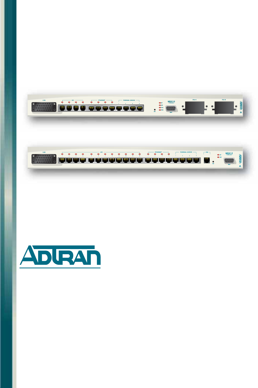
61189500L1-1F 1-1 Section 1IntroductionOVERVIEWThe MX410 (P/N 1189500L1) and MX412 (P/N 1189512L1) systems deliver full DS0 control to service locatio
MX410/MX412 System Manual1-2 61189500L1-1FFigure 1-3. MX410 OverviewFigure 1-4. MX412 Overview4 x 10/100 EthernetRedundant PowerCapabilityDB-9 Craft
Features61189500L1-1F 1-3FEATURESThe major features of the MX410/MX412 are as follows:• 19-inch wall mounting or rack mounting, one rack unit high• Fr
MX410/MX412 System Manual1-4 61189500L1-1FThis page is intentionally blank.
61189500L1-1F 2-1 Section 2Engineering GuidelinesGENERALThis section provides engineering guidelines for network designers who are incorporating an MX
MX410/MX412 System Manualii 61189500L1-1FFront Matt erTrademarksAny brand names and product names included in this manual are trademarks, registered t
MX410/MX412 System Manual2-2 61189500L1-1FPOWER REQUIREMENTSTable 2-3 lists the current draw at –48 VDC (operating range of –42 VDC to –60 VDC) and ±2
Power Dissipation61189500L1-1F 2-3POWER DISSIPATIONTable 2-5 provides the heat dissipation data at –48 VDC (operating range of –42 VDC to –60 VDC) an
MX410/MX412 System Manual2-4 61189500L1-1FThis page is intentionally blank.
61189500L1-1F 3-1 Section 3Application GuidelinesINTRODUCTIONThis section describes several applications for the MX410/MX412 system. For each appli-ca
MX410/MX412 System Manual3-2 61189500L1-1FMX410 DATA PATH BLOCK DIAGRAMAs shown in Figure 3-1, the MX410 contains a 1/0 cross connect that allows DS0s
MX410 Data Path Block Diagram61189500L1-1F 3-3Drop and Continue ApplicationThe following applies to Remote Site #1 shown in Figure 3-2. In the Drop an
MX410/MX412 System Manual3-4 61189500L1-1FSetupConnect the incoming DS1 (the DS1 from which the DS0s are dropped) to the DS1 1 RJ Connector. Connect
MX410 Data Path Block Diagram61189500L1-1F 3-5Figure 3-4 shows the Quick Setup menu after DS0s 21-22 have been dropped from DS1 1 to PPP1, DS0s 23-24
MX410/MX412 System Manual3-6 61189500L1-1FFigure 3-6 shows the Cross-Connect Mapping menu after the remaining DS0s have been continued to DS1 2 as wel
MX410 Data Path Block Diagram61189500L1-1F 3-7Drop and Insert ApplicationThe following applies to Remote Site #1 shown in Figure 3-7. In the Drop and
61189500L1-1F iiiRevision HistoryConventionsThe following typographical conventions are used in this document:This font indicates a cross-reference li
MX410/MX412 System Manual3-8 61189500L1-1FSetupConnect the DS1 from which the DS0s will be dropped to the DS1 1 RJ. Connect the other DS1 to which the
MX410 Data Path Block Diagram61189500L1-1F 3-9Figure 3-9 shows the Quick Setup menu after DS0s 23-24 have been dropped from DS1 1 to PPP1 and PPP 2 ha
MX410/MX412 System Manual3-10 61189500L1-1FFigure 3-11 shows the Cross-Connect Mapping menu after DS0s 1-12 are continued through from DS1 1 to DS1 2
MX410 Data Path Block Diagram61189500L1-1F 3-11Figure 3-13 shows the Cross-Connect Mapping menu after DS0s 13-22 are inserted in DS1 2 from DS1 4. Any
MX410/MX412 System Manual3-12 61189500L1-1FIntegrated Wireless Access Device or DS0 GroomingThe following applies to Remote Site #1 shown in Figure 3-
MX410 Data Path Block Diagram61189500L1-1F 3-13Figure 3-15. Bandwidth Efficiency with DS0 Grooming DiagramThe equipment needed for an Integrated Wire
MX410/MX412 System Manual3-14 61189500L1-1FSetupConnect the DS1 from which the DS0s will be dropped to the DS1 1 RJ Connector. Connect the other DS1s
MX410 Data Path Block Diagram61189500L1-1F 3-15Figure 3-17 shows the Quick Setup menu after DS0s 23-24 have been dropped from DS1 1 to PPP1, and PPP 2
MX410/MX412 System Manual3-16 61189500L1-1FFigure 3-19 shows the Cross-Connect Mapping menu after DS0s 1-7 are mapped from DS1 1 to DS1 2, DS0s 8-14 a
MX410 Data Path Block Diagram61189500L1-1F 3-17Figure 3-21 shows the Cross-Connect Mapping menu for DS1 3.Figure 3-21. Integrated Wireless Access Dev
MX410/MX412 System Manualiv 61189500L1-1FHAZARD CLASSIFICATIONSThe following hazard classifications are used in this document:NOTENotes inform the use
MX410/MX412 System Manual3-18 61189500L1-1FRemote Management of Other Systems using Terminal Server Ports and Ethernet ConnectivityIn this application
MX410 Data Path Block Diagram61189500L1-1F 3-19SetupFirst, connect the RS-232 craft port on the other equipment to the MX410 terminal server port. For
MX410/MX412 System Manual3-20 61189500L1-1FThis page is intentionally blank.
61189500L1-1F 4-1 Section 4InstallationGENERALThe first three tasks for installing and operating the MX410/MX412 are to unpack, inspect, and install.
MX410/MX412 System Manual4-2 61189500L1-1FRACKMOUNTFor a rackmount installation, perform the following steps:1. Ensure the mounting brackets to the MX
Rear Panel61189500L1-1F 4-3REAR PANELThe MX410/MX412 rear panel is equipped with wire-wrap pins for external auxiliary inputs, wire-wrap pins for alar
MX410/MX412 System Manual4-4 61189500L1-1FAlarm Contacts/Auxiliary InputsThe alarm contacts and auxiliary (AUX) inputs are shown in Figure 4-4.Figure
Front Panel61189500L1-1F 4-5FRONT PANELThe front panels for the MX410 and MX412 are described below.MX410The MX410 front panel (see Figure 4-5) is equ
MX410/MX412 System Manual4-6 61189500L1-1FV. 3 5 Po r tThe V.35 port is a Nx64k serial interface (up to 1.536 Mbps) with a CCITT V.35, 34-pin connect
Front Panel61189500L1-1F 4-7Ethernet PortsThe four Ethernet jacks, labeled ETHERNET, are located on the MX410/MX412 front panel. They provide LAN acce
61189500L1-1F vTrainingADTRAN offers training courses on our products. These courses include overviews on product features and functions while coverin
MX410/MX412 System Manual4-8 61189500L1-1FTer minal Ser ver PortsThe four Terminal Server port RS-232 interfaces located on the front panel are used t
Front Panel61189500L1-1F 4-9FXS PortThe FXS port (MX412 only) provides a 2-wire analog interface between a Voice Frequency (VF) transmission and a sig
MX410/MX412 System Manual4-10 61189500L1-1FLED IndicatorsThe LEDs on the front panel of the MX410/MX412 indicate the status of the power, DS1, Etherne
Turn-up61189500L1-1F 4-11TURN-UPThe following sections provide turn-up steps for applying power and logging in to the MX410/MX412.Power UpTo power up
MX410/MX412 System Manual4-12 61189500L1-1F• –48 VDC systems: –42 VDC to –60 VDC• –24 VDC systems: –22 VDC to –27 VDC• +24 VDC systems: +22 VDC to +27
61189500L1-1F 5-1 Section 5User InterfaceINTRODUCTIONThis section provides detailed information on the following:• “System Management” on page 5-1• “L
MX410/MX412 System Manual5-2 61189500L1-1F- No parity (none)-One stop bit- No flow control2. Set the PC for direct connect on the appropriate communic
Menu Structure61189500L1-1F 5-3MENU STRUCTUREThe menu structure for the MX410/MX412 is a layered menu tree. Each layer of the menu tree is displayed a
MX410/MX412 System Manual5-4 61189500L1-1FMENU LAYOUT AND NAVIGATIONFigure 5-1 illustrates the basic menu layout used in the MX410/MX412 menu system.
Menu Trees61189500L1-1F 5-5Basic menu navigation is accomplished by selecting the desired option number and then pressing ENTER. To return to the prev
MX410/MX412 System Manualvi 61189500L1-1F
MX410/MX412 System Manual5-6 61189500L1-1FFigure 5-2. MX410/MX412 Main Menu TreeUnit NameCLEI CodePart NumberSerial NumberProduct RevisionMAC Address
Menu Trees61189500L1-1F 5-7Figure 5-3. MX410/MX412 Provisioning Menu Tree2. V.35 Port1. Forced On2. Normal1. CTS1. Forced On2. Normal2. DCD1. Forced
MX410/MX412 System Manual5-8 61189500L1-1FFigure 5-4. MX410/MX412 Provisioning Menu Tree (Continued)A1A2Bold text indicates default3. Cross-Connect M
Menu Trees61189500L1-1F 5-9Figure 5-5. MX410/MX412 Provisioning Menu Tree (Continued)5. General1. 96002. 192003. 384004. 576005. 1152002. Create New
MX410/MX412 System Manual5-10 61189500L1-1FFigure 5-6. MX410/MX412 Provisioning Menu Tree (Continued)A31. IP Address2. Subnet Mask3. Apply SettingsNe
Menu Trees61189500L1-1F 5-11Figure 5-7. MX410/MX412 Provisioning Menu Tree (Continued)1. Trap Host IP2. Trap Host Method3. Trap Host Status7. SNMP8.
MX410/MX412 System Manual5-12 61189500L1-1FFigure 5-8. MX410/MX412 Quick Setup Menu Tree4. IP Address / Subnet Mask3. System IDNew System Name5. Defa
Menu Trees61189500L1-1F 5-13Figure 5-9. MX410/MX412 Quick Setup Menu Tree (Continued)B1DS1 1 (DS0 1 - 24)DS1 2 (DS0 1 - 24)DS1 3 (DS0 1 - 24)PortsDS1
MX410/MX412 System Manual5-14 61189500L1-1FFigure 5-10. MX410/MX412 Test Menu TreeBold text indicates defaultC1. Loopback1. 120 Minutes2. 90 Minutes3
Menu Descriptions61189500L1-1F 5-15MENU DESCRIPTIONSThe MX410/MX412 Main Menu (see Figure 5-11) is the access point to all other operations. Each Main
61189500L1-1F vii ContentsHazard Classifications . . . . . . . . . . . . . . . . . . . . . . . . . . . . . . . . . . . . . . . . . . . . . . . . . .
MX410/MX412 System Manual5-16 61189500L1-1FConfiguration ScreenThe Configuration Screen (see Figure 5-12) displays information about the MX410/MX412.
Menu Descriptions61189500L1-1F 5-17Code Checksum This field displays the checksum of the current firmware revision level of the MX410/MX412.Boot Versi
MX410/MX412 System Manual5-18 61189500L1-1FProvisioning MenuThe Provisioning Menu (see Figure 5-13) is used to configure and change the operating char
Menu Descriptions61189500L1-1F 5-198 System Configuration Archive (SCA)This option displays the “SCA Update Menu” on page 5-51.9 Save Provisioning Thi
MX410/MX412 System Manual5-20 61189500L1-1FDS1 Ports MenuThe DS1 Ports menu (see Figure 5-14) displays line length, line coding, loopback detection, f
Menu Descriptions61189500L1-1F 5-21The DS1 Ports menu options are listed in Table 5-5.Table 5-5. DS1 Ports Menu OptionsOption Description Function1 D
MX410/MX412 System Manual5-22 61189500L1-1FDS1 Provisioning MenuThe DS1 Provisioning menu (see Figure 5-16) is used to set the line length, line codin
Menu Descriptions61189500L1-1F 5-23Alarm Pass Thru2 Line Coding This option sets the line code for each individual port interface to match the connect
MX410/MX412 System Manual5-24 61189500L1-1FPrimary Timing Mode MenuThe Primary Timing Mode menu (see Figure 5-17) is used to set the primary timing mo
Menu Descriptions61189500L1-1F 5-25Secondary Timing Mode MenuThe Secondary Timing Mode menu (see Figure 5-18) is used to set the secondary timing mode
MX410/MX412 System Manualviii 61189500L1-1FRackmount . . . . . . . . . . . . . . . . . . . . . . . . . . . . . . . . . . . . . . . . . . . . . . . . .
MX410/MX412 System Manual5-26 61189500L1-1FV.35 Port MenuThe V.35 Port menu (see Figure 5-19) is used to provision the V.35 Port.Figure 5-19. V.35 Po
Menu Descriptions61189500L1-1F 5-27Cross-Connect Mapping MenuThe Cross-Connect Mapping menu is used to display DS0 information for the four DS1 ports
MX410/MX412 System Manual5-28 61189500L1-1FThe Cross-Connect Mapping menu options are listed in Table 5-10.Table 5-10. Cross-Connect Mapping Menu Opt
Menu Descriptions61189500L1-1F 5-294 Frame Relay This option invokes the Change Cross-Connect Mapping menu, which is used to provision the frame relay
MX410/MX412 System Manual5-30 61189500L1-1FTerminal Server Ports MenuThe Terminal Server Ports menu (see Figure 5-22) is used to select Terminal Port
Menu Descriptions61189500L1-1F 5-31Terminal Server Port (1 - 4) MenuThe Terminal Server Port menu (see Figure 5-23) is used to provision the Terminal
MX410/MX412 System Manual5-32 61189500L1-1F6 Password This option is used to assign a password to the selected port number for use when security is en
Menu Descriptions61189500L1-1F 5-33General Provisioning MenuThe General Provisioning menu (see Figure 5-24) is used to provision the craft port Baud r
MX410/MX412 System Manual5-34 61189500L1-1F5 Auto-Logoff Inactivity TimeThis option defines when a menu session automatically terminates due to inacti
Menu Descriptions61189500L1-1F 5-35Network Management MenuThe Network Management menu (see Figure 5-25) is used to provision network information.Figur
Contents61189500L1-1F ixNetwork Management Menu . . . . . . . . . . . . . . . . . . . . . . . . . . . . . . . . . . . . . . . . . . . . . . . . . . .
MX410/MX412 System Manual5-36 61189500L1-1FEthernet MenuThe Ethernet menu (see Figure 5-26) is used to provision Ethernet information.Figure 5-26. Et
Menu Descriptions61189500L1-1F 5-37N/A MAC Address This read-only field displays the Medium Access Control (MAC) Address. MAC Addresses are location-i
MX410/MX412 System Manual5-38 61189500L1-1FPPP BCP/IPCP MenuPoint-to-Point Protocol (PPP) is commonly used for LAN extension and Remote management con
Menu Descriptions61189500L1-1F 5-39The PPP BCP/IPCP menu options are listed in Table 5-16.Table 5-16. PPP BCP/IPCP Menu Options Option Description Fu
MX410/MX412 System Manual5-40 61189500L1-1FDHCP Server MenuThe DHCP (Dynamic Host Configuration Protocol) Server menu, shown in Figure 5-28, is used t
Menu Descriptions61189500L1-1F 5-41Frame Relay MenuThe Frame Relay menu, shown in Figure 5-29, is used to provision the frame relay. Use T to toggle t
MX410/MX412 System Manual5-42 61189500L1-1FFrame Relay Type MenuThe Frame Relay Type menu, shown in Figure 5-30, is used to select the frame relay typ
Menu Descriptions61189500L1-1F 5-43View Frame Relay MenuThe View Frame Relay menu, shown in Figure 5-31, is used to select a VC for viewing and provis
MX410/MX412 System Manual5-44 61189500L1-1FFrame Relay Port MenuThe Frame Relay Port menu, shown in Figure 5-32, is used to provision the selected VC.
Menu Descriptions61189500L1-1F 5-45Network Mode MenuThe Network Mode menu, shown in Figure 5-33, is used to provision the network mode.NOTEChanging th
Verwandte Produkte und Handbücher für Vernetzung ADTRAN MX410
 (24 Seiten)
(10 Seiten)
(30 Seiten)
(50 Seiten)
(26 Seiten)
(386 Seiten)
(10 Seiten)
(20 Seiten)
(236 Seiten)
(142 Seiten)
(15 Seiten)
(111 Seiten)
(13 Seiten)
(24 Seiten)
(10 Seiten)
(30 Seiten)
(50 Seiten)
(26 Seiten)
(386 Seiten)
(10 Seiten)
(20 Seiten)
(236 Seiten)
(142 Seiten)
(15 Seiten)
(111 Seiten)
(13 Seiten)
© 2020, manymanuals.de. Alle Rechte vorbehalten. | 1.888 s |
 Manymanuals.com
 Manymanuals.de
 Manymanuals.fr
 Manymanuals.it
 Manymanuals.pl
 Manymanuals.cz
 Manymanuals.es
 Manymanuals-pt.com
Kommentare zu diesen Handbüchern